|
|
 |
 |
 |
 |
| |
Detecting Temperature Differences on PCB Components
20
September
2016
|
| |
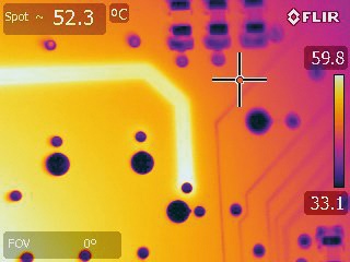 High-performance FLIR T420 cameras detects faults in PCBs in an early stage. The design of a Printed Circuit Board (PCB) can be very complex. Dutch embedded electronics specialist 3T sometimes develops PCBs that have over 2,000 different components. But what if something is wrong with one of those components? How can you see tiny faults in PCB components of less than a millimeter that might be the cause for a bigger PCB failure? Very often, thermal imaging will be the answer. 3T has been using thermal imaging cameras for many years throughout its different activities to detect hot spots of less than 125 microns.
3T is a leading Dutch developer of electronics and embedded systems. With an all-round team of approximately 50 employees, 3T is one of the larger providers in the Netherlands. The company has offices in Enschede and Eindhoven and has been active for 25 years in a number of demanding market segments, including machinery, professional equipment, instrumentation for measurement and testing, communications systems, innovative consumer products, and medical products.
We are using thermal imaging cameras throughout our entire process, says Ronald van der Meer, hardware engineer at 3T. When something goes wrong in a PCB, be it improper soldering of a circuit or a failing component, the PCB will heat up. Therefore, thermal imaging is a very good way to diagnose PCB boards in an early stage of a problem. We use it in the design phase of a PCB, to test it before it is supplied to the customer or in the qualification stage.
Benefits of thermal imaging for micro-electronics
3T recently opted for the FLIR T420 bench test thermal imaging camera with 50µm close-up lens. This close-up lens was absolutely necessary, because without it the focus distance was too big, says Ronald van der Meer. We are dealing with micro-electronics here at 3T. The mass of the PCB components that we need to research is so little, and possible temperature changes are so small, that we really need that detail.
The alternative for thermal imaging in the field of PCB electronics is the use of thermocouples, a temperature-measuring device consisting of two wire legs that contact each other at one or more spots. Although thermocouple measurements are still required by certain regulatory bodies, the problem with thermocouples for measuring micro-electronics is that these devices can actually disturb the measurement, because they need to make contact with the tiny components on the PCB board, says Ronald van der Meer. Thermal imaging on the other hand is a non-contact technology, so you dont have that problem.
FLIR T420 bench test thermal imaging camera
3T has been convinced of the power of thermal imaging for many years. And now that prices of thermal imaging cameras are dropping, thanks to high unit shipment, owning a thermal imaging camera becomes even more attractive for research and electronics design companies.
The FLIR T420 is a high-performance, yet affordable thermal imaging camera. It combines excellent ergonomics with high image quality of 320 x 240 pixels. The FLIR T400-Series come with a tiltable optical unit which makes it possible to measure and take images of objects in all angles, still in a comfortable working position.
The T420 camera is very robust and easy to carry, says Ronald van der Meer. That is very convenient, because we sometimes use our camera on the customer site. Especially with the close-up lens, the image detail is very good, so this allows us to see the smallest faults. PCB boards are also usually multi-layered. Sometimes, due to a production error, the different layers come apart. These delaminations then form small air bubbles, which can be discovered, as the FLIR thermal imaging camera picks up small temperature differences located around these bubbles.
FLIR software for R&D applications
For 3T, FLIRs ResearchIR software for R&D applications was an essential part of the thermal imaging package. ResearchIR allows researchers to make high speed recordings and perform advanced thermal pattern analysis.
Sometimes, we need to capture the precise response of a one-time thermal event, says Ronald van der Meer. This would be difficult to capture in one still image. That is why the ability to make high-speed video images is critical for us. Recording a certain event helps us to reconstruct and analyze the problem more accurately. We also import our video images obtained with ReserachIR into MATLAB, a software package for data visualization, and programming that we use.
ResearchIR allows 3T engineers to better analyze PCB hot spots and find thermal peaks. The software gives users complete colorization control, so they can change the color palette, color distribution, contrast and isotherms, zooming and panning.
For more information, please contact:
FLIR Systems
Luxemburgstraat 2
2321 Meer
Belgium
Tel: +32 (0) 3665 5100
Fax: +32 (0) 3303 5624
Email: flir@flir.com
Web: www.flir.com |
|
|
| |
FactoryEquipment.com are not responsible for the content of submitted or externally produced articles and images.
Click
here to email FactoryEquipment.com about any errors or omissions contained within this article. |
| |
|
|
|
|
|
|